Carvey Update
PCB Layout
After stripping down the controller I’ve settled on a path forwards with the replacement design. Top of the list is getting all of the components mounted up within the same space. Thsi is important as the old main board is enclosed within a steel housingm located at the rear of the main enclosure, which provides protection whaever else is going on inside.
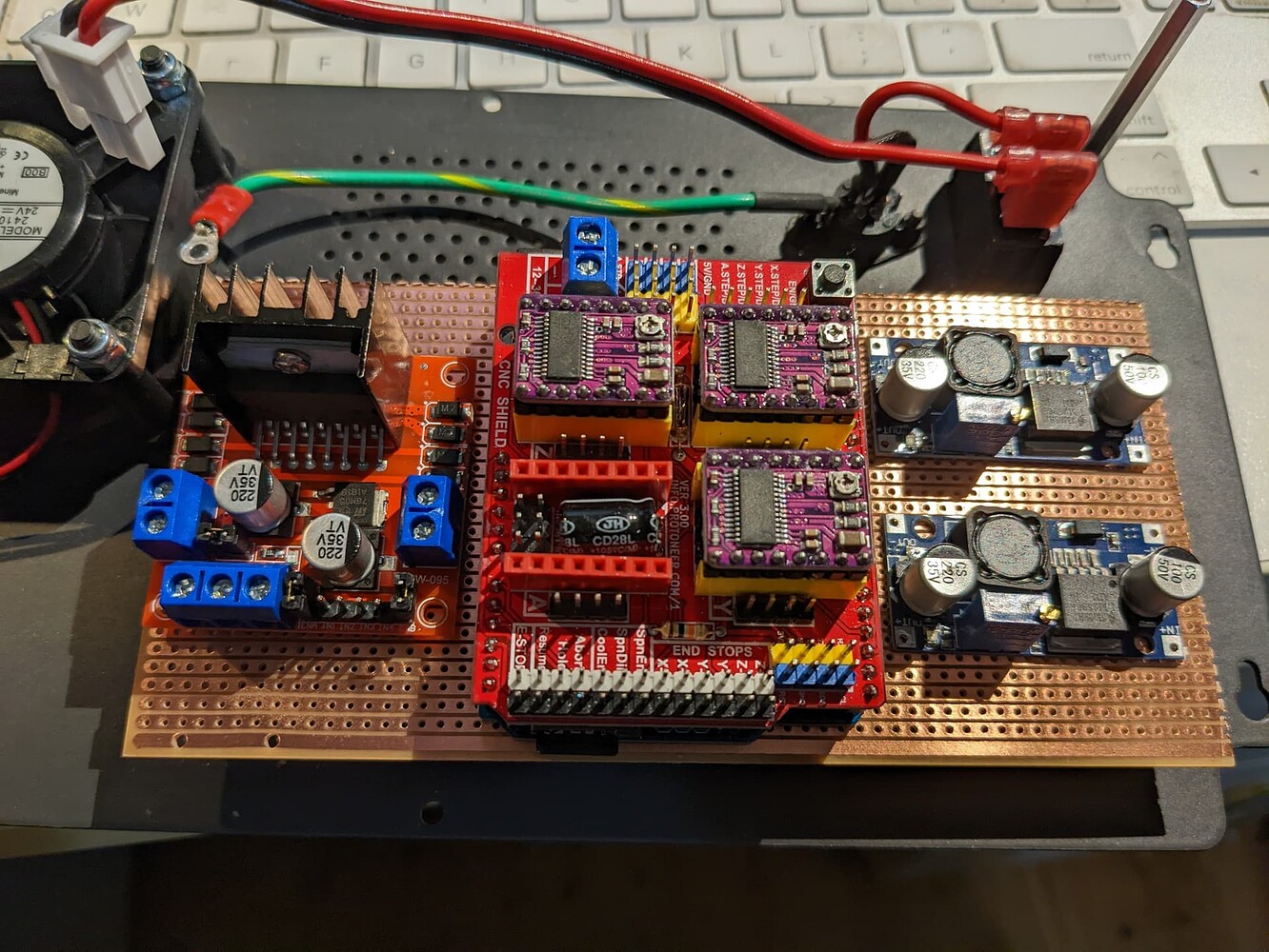
So I’ve taken a look at the layout of the components. I cut out some veroboard that fits inside the case to use as a base. There’s two buck style dc-dc power converters to regulate the 48v supply down to 24 and 5v. (The ECU uses 5v and the LEDs are 24v.) Then there’s the ESP32 ECU along with the CNC shield and lastly the PWM spindle controller. At this stage I don’t think I need a relay as sending 0v to the PWM should stop the spindle but I may need to add one. If I want to electrically isolate the spindle when the machine is in stop mode then I’ll need to add one.
It is alo possible not use spindle speed control. The PWM control board cold be replaced with a relay and the spindle ran at full speed (48v). I guess this is largely governed by what materials need to be cut.
My basic plan is to use the veroboard to mount everything on using PCB standoffs, and use the tracks for the 48/24/5v DC supply busses that all of the components can tap into. Most of the enclosure wiring connects direct to the CNC shield so for that I plan to change the existing molex connectors to 2mm pin connectors. The pin connectors might not be as robust as the clip in style molex connectors but they can easily handle the current and are working absolutely fine in millions of CNC’s and 3D printers worldwide (are there millions of them?? who knows). Of course you could get fancy and add molex style sockets to the veroboard and then connect the veroboard to the shield but all that’s really doing is doubling the work and doubling the number of potential failure nodes. A better option would be a purposed made PCB that everything plugs into but it’s simply not worth the effort.
I’m going to try and repurpose the existing USB socket so that from the outside there is no physical change, I should be able to mount this to the veroboard, hence the reason that the copper side of the board is upwards. I’ll connect the pins to a cut down USB cable which I will simply plug into the ESP-32. Ultimately the machine runs untethered via WiFi so the USB is little used, but it’s handy for updates or those times you might need to connect direct.